How To Make Hair Brush In Fusion 360 | Fusion 360 Tutorial
- Posted on 07 January, 2022
- 6D Hair Extensions
- By Anonymous
hello everyone
today we will be making a hair brush design in AutoDesk Fusion 360 .
There are various ways to make such complex structures in a 3D application like solidworks and fusion 360, hope you guys will enjoy the video, do comment any suggestions and queries for my upcoming videos and don't forget to share and subscribe my channel.
SUPPORT ME - https://www.paypal.me/sparkplug99
GOOGLE PAY - muammarqazzafi@oksbi OR +917785814333
my Fiverr account - https://www.fiverr.com/s2/b634f35e55?u...
This video will focus on improving the beginners skills in fusion 360.
This is nice exercise to put to practice what we have learned so far.
In this video you will find about basic use of commands like extrude, fillet, chamfer, loft , trim , stitch , sweep and creating sketch.
WATCH MY SERIES ON BEGINNERS EXERCISE
Exercise #1 -https://youtu.be/lqZmiI-xIOo
Exercise #2 - https://youtu.be/P7zDpnu7BWI
Exercise #3 - https://youtu.be/ViOTQG57IAI
Exercise #4 - https://youtu.be/91b5yn_8Xeo
Exercise #5 - https://youtu.be/yUDea8COQsM
Exercise #6 - https://youtu.be/Of-S_uDVAik
Exercise #7 - https://youtu.be/dMpoXyeSa0o
Exercise #8 - https://youtu.be/RhNyVek7pkg
Exercise #9 - https://youtu.be/9xOI7pl5pkQ
Exercise #10 - https://youtu.be/g7B6wppi7RM
Exercise #11 - https://youtu.be/VRy7cN70OaQ
My official email ID- [email protected]
Fusion 360 helps students and educators prepare for the future of design. It's the first 3D CAD, CAM, and CAE tool of its kind, connecting your entire product development process into one cloud-based platform. Download the software today, then turn your ideas into reality.
Download AUTODESK FUSION 360 - https://www.autodesk.com/products/fusi...
#fusion360 #autodesk #practice #exercise #practice #fusion360engine #fusion360piston
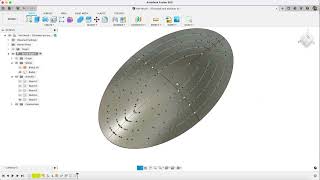
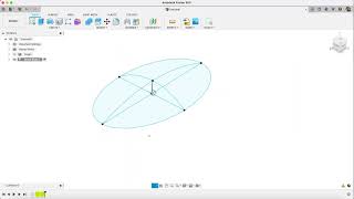
Hey guys and welcome back to another video of uh uh video or spark plug. So in this video tutorial, i will be showing you how to make this um beautiful, uh hair brush. What you call this, i i don't know: hair brush infusion 360., so hope you guys will enjoy the video. Basically, the all the concepts are quite similar. This is a simple extrude, but the tricky part is to make these uh hair brushes. You know the spikes here. So i will show you: let's get started we'll start by making the base. First then, in the later part of the video we will be making this curve the red one and in the final part we will be making the spikes here. So let's get started so new work, space, click on the top plane or the bottom view, and go to create, go to ellipse and from the origin draw an ellipse. Let'S say the dimension was the major diameters is 110. Ah, okay, let's see draw an ellipse like this press d and make the major diameter as 110 and the minor diameter as 55. Now, press c again and on this very line draw two circles like this press d for dimension the outer it will be having 26 mm dia, while the inner would be having 9 mm dia now once done, join these two lines. Uh from this point. To this point, press d again and make the dimension of this line as 200 mm, like this press l again and from this point to this, draw a taper line like this and from constraint. Click on tangent constraint, select this line and this circle to make the tangent relationship between them press d again like this line and the center line and give the angle here as 4 degrees now once done, just mirror this line across this line and press ok. Now, once done just finish, the sketch click on extrude select these profiles. Okay, this! I don't know why, but this is just not closed, so let me just check it why it's not closed? Okay, why it's? Okay, one thing: uh make this circle coincident to this line. Now we have a closed sketch here, extrude it like this up to, let's make it a new component and the extrusion distance would be 10 and press. Ok, press shift and n to enables the colors now again click on this sketch and we will start by making another ellipse. So click on ellipse and from origin again draw an ellipse like this press d. Again, the major diameter this time would be 95, whereas the minor would be, let's say, 45 yeah. This seems fine and finish the sketch and extrude cut it up negative downwards. Minus 1 mm, like this now, click on offset plane and offset this plane up to a distance of 12 mm like this and create a sketch on this point draw a line like this any dimension. We just need this point and there's an option called point. So on this point draw a point like this, so we have a a point here. You guys can see in 3d here just finish the sketch. Now we have a point here. This line is not necessary. We just wanted the point, but the problem is sometimes due to graphics issue or something if we just create point on this case, sometimes it's visible or it's not maybe there's a glitch in the fusion. So this is why that is why i've drawn the line here. Go to create, there's an option called loft, select this profile and select this point: you can see it created a pyramid like a structure, but the point two is you guys can see the profile. Two is our point, so this is sharp. Just can you tangent and just press? Ok, you don't have to deal with any of them and just press ok. So we have a dome like structure here now go to fill it select this point and this point and make a fillet of 0.5 like this. Now again create a sketch on this profile. What we are going to do is create an offset and select this outer curve and make an offset of minus 3 inside. So we have a curve here now we are going to make some extra ellipse here so draw some ellipse. The number of ellipse that we will be drawing is total number of three ellipse apart from this um um, so counting this one will be four, so just hide the component for now. So one ellipse, this one is second, and this one is third, so the uh first one this is going to be 80. and the minor diameter of this is going to be 30. Now, as for the second, this dimension is going to be, let's say, 20, whereas the major diameter of this ellipse is going to be 65. As for the bottom is concerned, the inner one, this is going to be 45, whereas the minor dial is going to be 12, less yeah everything's good. So we have a one dimension to have here and here from the center of course, and three dimension. We have here now again draw a line from this point to this point and make this line mirror so go to constraint. Go to symmetry select this point both the end of the line and select the center line, so we have a mirror line so press d and give the dimension of this line as 28 mm. So we have a 28 mm length line in the center. Now. Just finish the sketch for now now just bring back the component here, so we have a uh sketch here again, so click on create a sketch again display. Now we need, i need you to move it to an isometric view for a better result, go to create. Go to project and there's an option called project to surface select on this. The surface is going to be this dome and the curve select each curve, the first one, the second. No not this point. Only the curve select only the curve carefully, all four of them yeah. So we have a four cup and, of course, the center line that we have drawn here and the project link. You can keep the project click here. It will get linked to your sketch. If you change make any changes to this sketch, so that will occur there also. So just if i just hide the previous sketch you can see, we have projected all this ellipse onto this surface. Beautiful. Isn'T it now uh once this this? What the purpose of this ellipse this will uh! You know this will act as a path to make all these uh spikes here, okay, so what i'm going to do is again just finish the sketch, so we have a sketch here now: click on create a sketch and on the center plane you can just click On slice, so we have a you guys can see. If i just hide the component here, you guys can see one two, three four and the fifth one is here, of course. Now these are the what you call as the projections here. So we will start by making a line uh for that, so you just hide this. For now, we have one two three four um five curve here, so press p for project and select all these curves here and this one also and just break the approach you can change, bring down the project link and just hide the body for now now select All these lines, all these four curves and right click on it and there's an option called normal, so just make it in um, just switch them in construction mode. Now, press l again and draw a line like this, give the dimension the aligned one of length. 15 mm to drag it like this, just zoom a bit out and press go to constrain coincidence, make this point coincident with this line, so you can drag it like. This now bring back your brush here, press d again and the angle between these two lines. This is going to be 55. You can still drag this up to this curve, but i need you to just put it on the outermost side like this: leave it there. Okay, now there's an option called two point circle and make a circle of like two point. Like this, make it the center coincident, with this line press d again and give this a dimension of mn like this and from this point, draw a uh press, l again and from let's say this point, draw a tapered line up to a little bit more than This point: what i'm going to do is press d again and from this point to this line, the vertical dimension is going to be 0.5 and the angle between these two is going to be two degrees. You know, okay, let's see what i'm going to do. I have just created a section profile of a spike, so i'm going to revolve this with this slide, you will see in the later part of the video. If i just click on component, i need you to extend it further downward so that when i revolve it gets joined with the solid body, the green one we have already created so just replace l again and click on these two point to close the sketch okay. So now the next step is to repeat the same step for all these four curves, so i have done the first. You can do it with the second third and the top one also so, let's i will show you example again draw a line. Give this a length of 15 make it coincident. With this point, everything will be same. Only the difference is going to be the angle. The first angle was 55 degrees, whereas the second will be 65 degrees and the rest. All the profile will be same draw a two circle, two point: make it coincident with the center line press d and make the dias 2 press l again draw one paper line like this pressed uh press d and make the angle between these two line as two Degrees and the distance from this point to this point as 0.5 degrees. Now it's a bit longer than this, just press l again and join these two now repeat the same step for the third portion also uh make the line. Dimension is 5 15, and this time the angle is going to be 70 degrees yeah. So we have one 155 uh. This one glitch with the software here go to two point again: make it coincident press d make the dial two press l again draw a taper line like this press d for dimension and mark the angle as 2 and from this point to this point, make this F5, make it little bit longer and join those two lines again. As for the center line, also repeat the same process, press l, this time, the y line would be vertical, make it 15. This point to this point two point circle like this: make it coincident press b, make it two press l from this point to this point and the angle is going to be 2 degrees and this distance is going to be 0.5, as you guys can see. It'S a little bit longer here. So let's join this. We have a four hour stitch here and if i just show you this is how this will look like now. Just finish the sketch. What i'm going to do is we have a closed sketch here. So just go to revolve, select first profile like this and select it as the middle axis and the operation will be joined and we have our uh first spike here. Right, just bring back the sketch again repeat the same for all four profile. Just make sure the operation is joined so that it gets joined with the mother part join and ask them the last also just make it join like this uh. Basically, it's up to you. I have chosen to make it before if you think that the gap here is too much, you can also create a one layer here. Also the process remains the same. Only difference is that i have chosen four number of ellipse each for every curve. Uh you guys can have additional ellipse, also so just hide the sketch and bring back the previous skill that represents the path. Now the switch to isometric view. We will start by the outer ring. So let's go to circular pattern and the type no go to create. Go to pattern, go to pattern on path and type select the type as features select. The first revolve feature here: okay, one more thing that i think that i have missed uh this profile, the bottom one here. So what i'm going to do is: let's just make this sketch here. If i just hide it, you guys can see this. One still remains here, so repeat the same step for here also just make it 15 uh click on coincident and make it coincident with this one. Okay, something is wrong here. Okay, i forgot to make it project so click on project and make it project like this. Just hide the sketch right click on this and make it normal construction press see this point select this line and this line and make it like this here. Let me just track the angle here now: uh one more thing that if i i forgot to make the first one, therefore, the angle 55 is supposed to be of this one, so repeat the same step. We will deal it with the lycra, so let's d again make this angle as 55 just make that edit, the second one as 65, this one as 70 and the last one as 80, now repeat the same step that we have done earlier. Ah, go to sketch two point circle make us two point circle like this: make it coincident press d again entire d and one taper line like this d again, and this dimension is going to be 0.5 and the angle between them is going to be 2 degrees. Make sure it's a bit longer and then press l again and like this and just finish this sketch now just bring back the body and the last sketch and one more revolve. You need to do so. Just bring back go back to timeline here and make a revolve uh here, the same step that i we did earlier. Click on join and bring back the timeline to this point. So we have our first revolve here. Okay, now once done just hide the sketch and bring the sketch with all the paths that you have, so we will start by go to pattern on path. Click on the future and the first select the path as this. Now, what i'm going to do is select the type as extend and you don't have to. We don't have the dimension to extend so i'm going to drag it the arrow to the point. It begins like this, so you guys can see it. The distance is approximately 213.33 when uh, so what i'm going to do is i'm just make it lesser like this so and if i just make the quantity here, let's say: let's make the quantity 40. You can also alter the quantity any time, so the orientation would be a long side path and you can just for select for the optimize and press ok. This will take some time as, according to your system performance, let's just wait for my system to respond. Okay, something's definitely wrong here. Let me just try again this. I think i have you know, done something wrong, so, let's just start again go to solid and planning our path. This first one - and this is going to be like this - the orientation would be alongside path. Okay, i don't know why it's not working this time. Let me just check what could have gone wrong. It'S working when we are doing the identical tie, but start working with the part direction. Let me just check, let me just go for the second one and just to check what could have been wrong and select on the profile here. Okay, this one is working. So what will we do? We will start by doing this one, i think, there's something wrong with the part of that. So just drag it like this up to this point, so we guys can see it's 99.25 and just make it 99 2.4, and this time let's say the quantity seems to be 30 30 seems working and just change the orientation to part direction and press. Ok. Now wait for your system to respond. This is how it will look. Now again, we repeat the same step for the third one: select the path as okay. I think i have missed something again. This revolve is not on the path. So let me just check the last sketch that we have drawn here. I think we have misplaced them, so let's just go back to those sketches right, click on this and edit okay. This is this move from just drag it uh to the end of the curve. Right and you know just finish the sketch - maybe that's the same issue with the this curve - also so just drag it up to end and finish the sketch. Now, let's try again just hide. This remains only the path so pattern on path. This time. The third revolve and repeat the same step: let's just go back to top view, just drag it like this up to the starting point. So starting point is 155.2, so just make it a little bit lesser and this time let's say the quantity was 30. So, let's make it 25, i think, and just go to part direction, and this is all up to you again. You can increase or decrease top quantity you want now. This is just to illustrate you. The tricks now two done two more to go now: go for the fourth one, select the profile and drag it up to a starting point, make it a less one mm and let's make the quantity 20, and this is going to be the part direction and press. Ok, this seems fine. Now, as for the last one select on this revolve, the path is going to be this one: let's try and make it symmetry. Okay, i think quantity 4 would be okay or, let's make it 5. Yeah 5 seems fine, make it part direction and press ok, yeah. The five seems like: let's try again the first one. I think this one there might be some issue with the curve or there might be some glitch with this region 360.. So, let's make again, let's try that again, let's see what we are doing wrong here. Basically, i can see the problem is. The problem is, if i just selecting the path direction, i don't know why it's not taking that. So i think uh that might be the you know, curve issue. Let'S try making uh selecting this. Let'S say: okay, okay, okay, the i there was a path issue, so i have what i have did what i have selected. This part is stop this. So, let's just switch back to top view and you guys can see it's working here so just go back to this and decrease it by 1 mm and just increase. So let's make it. Let'S say: 45 45 seems fine and press okay. So, okay, that was something uh with the curve. I think this might there might be some issue with the curve. Let'S just hide the sketch here. So we have completed designing the grills. Only thing left is, to just add some radius here, so let's make it a radius of 8 dmm like this and press up again for fillet. Select this point this point and make a fillet of 3mm like this beautiful and you can also add half some tricks. So now, as per you can shift and to enable the color, what i have done is i have manually selected took me around 5 to 10 minutes. I have manually set it all this point and added uh. You know manual appearance to each of the knobs of the spikes, so this looks amazing, so hope you guys will enjoy don't forget to share and subscribe. Thank you and have a nice day.
Comments
FPV KEV: Very good. I got a bit stuck early on with the projection and construction lines but soon got it to work. Glad to see you back on Fusion and look forward to the next project as I am nearing the end of a 10 part pencil sharpener project on Autodesk Fusion 360.
not supsresthtnt: Hello, Im trying to do the projection of the elipses into the surface (7:25) but it says error in the geometry. I have followed your instructions ad dimensions properly. Please help me to solve the probelm.
Pal Sih: Please make a video series teaching how to create car with fusion 360.
Khalimero Egg: Great!
Zehab Din:
Joe Guzardo: who is practicing the digeridoo?
Sang: